Earlier we did a project with an infrared distance measurement project with the GP2D12 module from Sharp. This is a good solution for indoor projects and can detect objects up to 80 cm. To detect objects further away we can use an ultrasonic ranging Module. Also the HC-SR04 is cheaper than the GP2D12. In this project we are going to use the HC-SR04 ultrasonic ranging module with an Arduino.
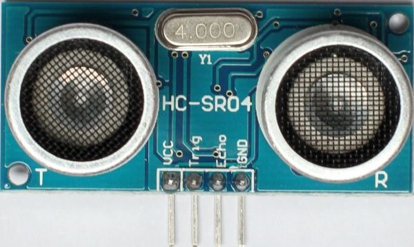
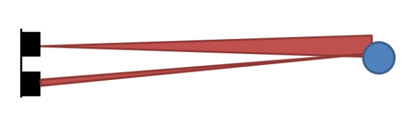
The HC-SR04 uses sound instead of light as the GP2D12 module does. The HC-SR04 sends a ping as a submarine does and measure the time between sending and receiving anything back when an object is in front of the sensor. Because using sound for its measurements we can reach up to 4 meters. The module is about 45x20x15 mm in size and has a 4 pin connection. Two pins are needed to power the module with 5 Volts. The working current is about 15 mA. One pin is the trigger ping and the last one is used to read the result of the measurements, the echo pin. The measuring angle from the HC-SR04 is 15 degree. At 4 meter distance this should be a beam of about 1 meter. At 1 meter this is 26 cm so we have to keep this in mind when using this information.
One ping of the HC0SR04 actually exists of 8 pulses at 40 kHz to do the measurement. To start a ping you need to provide a 10us pulse on the trigger input. When the distance is measured by the 8 pulses the HC0SR04 puts a pulse on the echo pin. You can calculate the distance with the length of the echo pulse and the speed of sound. The speed of sound is 340 m/s or 2.9 micro seconds per mm. We have to divide the length of the pulse by 2.9 to get the result in mm. The ping is traveling towards an object and back to the sensor again. Because of this we need to divide the result by two. Between two pings we need to keep a 60ms measurement cycle.

The connection of the HC-SR04 to an Arduino is really straight forward. Just connect the 5 volt and the ground to the outer pins. In this example the trigger pin is connected to 8 and the echo pin to the 9 of the Arduino. The image above was made with Fritzing available at Fritzing.org. You can also find the schematics over there.
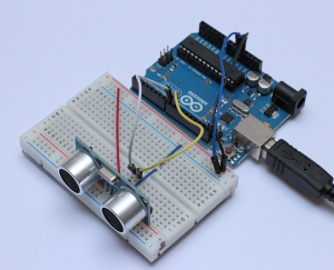
In real life this is the setup I used in my case. Beware of the little difference between the photo and the schematic above. I rotated the HC-Sr04 180 degree to let it face it to the edge of the board.
Arduino Code
/*

HC-SR04 for Arduino
Original project from https://swanrobotics.com
This project demonstrates the HC-SR

The distance presented in the code is in mm, but you can uncomment the line for distance in inches.

The schematics for this project can be found on https://swanrobotics.com
This example code is in the public domain.

*/
const int TriggerPin = 8; //Trig pin

const int EchoPin = 9; //Echo pin

long Duration = 0;
void setup(){

pinMode(TriggerPin,OUTPUT); // Trigger is an output pin

pinMode(EchoPin,INPUT); // Echo is an input pin

Serial.begin(9600); // Serial Output

}
void loop(){

digitalWrite(TriggerPin, LOW);

delayMicroseconds(2);

digitalWrite(TriggerPin, HIGH); // Trigger pin to HIGH

delayMicroseconds(10); // 10us high

digitalWrite(TriggerPin, LOW); // Trigger pin to HIGH
Duration = pulseIn(EchoPin,HIGH); // Waits for the echo pin to get high

// returns the Duration in microseconds

long Distance_mm = Distance(Duration); // Use function to calculate the distance
Serial.print("Distance = "); // Output to serial

Serial.print(Distance_mm);

Serial.println(" mm");
delay(1000); // Wait to do next measurement

}
long Distance(long time)

{

// Calculates the Distance in mm

// ((time)*(Speed of sound))/ toward and backward of object) * 10
long DistanceCalc; // Calculation variable

DistanceCalc = ((time /2.9) / 2); // Actual calculation in mm

//DistanceCalc = time / 74 / 2; // Actual calculation in inches

return DistanceCalc; // return calculated value

}
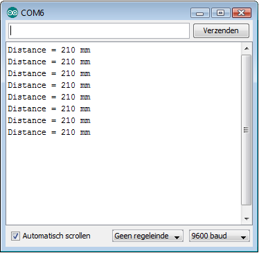
Screen shot of the serial monitor in the Arduino IDE.
Sources:
http://www.elecfreaks.com/244.html
http://arduino.cc/en/Tutorial/Ping
http://www.fritzing.org